Application Notes

Aircraft & Aerospace Sensors

Space Qualified Sensors

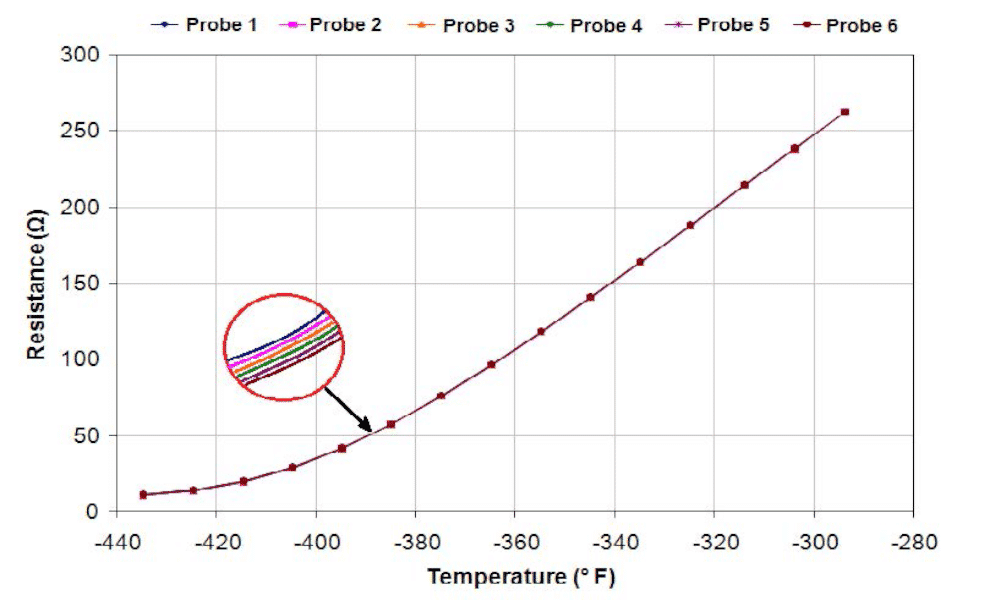
RdF has proudly every manned U.S. space mission beginning with NASA’s earliest flights.

Thousands of RdF’s designs are currently in orbit on satellites, telescopes, and the International Space Station (ISS). Their RTD’s, Heaters, Thermocouples, Reference Junctions, and other components are qualified to the most rigorous environmental conditions, these include:

  • RTDs for Cryogenic Fuels, Rocket Nozzles, Vehicle Structures and Skins
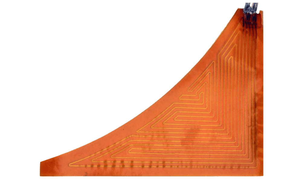
  • Sensors and heaters for electronics
  • Sensors for re-entry shields
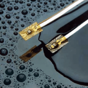
  • Low outgassing and low mass construction
  • Catalog Sensors with Flight Heritage
  • Proven performance in high shock, vibration and flow

Testing Instrumentation

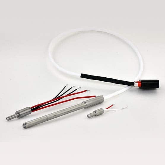
RdF provides RTDs, Thermocouples, Heat Flux, and Thermal Sensors used on a wide range of testing in flight, on test stands and in laboratory settings.
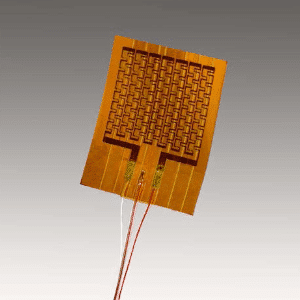
RTDs:

  • Temperatures cryogenic to 480°C (900°F)
  • Probes and capsules as small as 0.066” (1.7mm) OD
  • Surface mount design with a thickness of <1.27mm (0.05”)
  • Secondary standards accuracy, NIST-traceable calibration

Thermocouples:

  • Used cryogenic to 1150°C (2100°F)
  • Probes and surface mount configurations
  • Foil TCs as thin as 13μm (0.0005”) for response in milliseconds
  • Special limits of error–types E, J, K, T
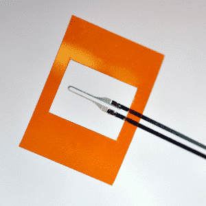
Heat Flux Sensors:

Thin Foil Gauges

  • Flexible
  • As thin as 76μm (0.003″)
  • Response time <0.1 seconds
  • Range 0-50 BTU/Ft2 sec

including Calorimeters and Radiometers

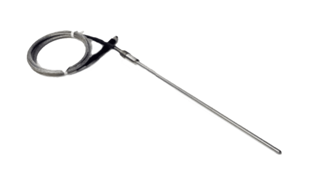
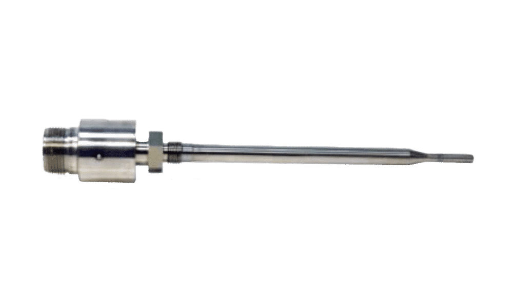
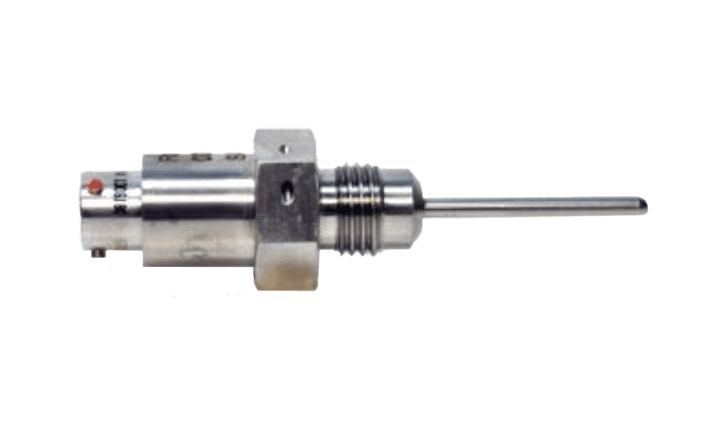
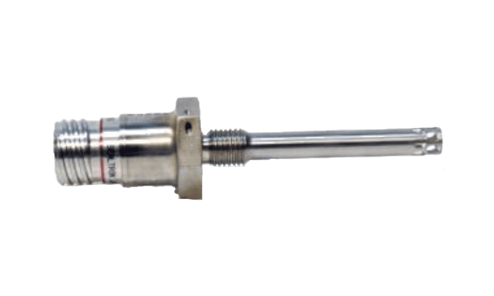
RdF Corporation is the world’s leading innovator in the design, development and production of surface, insertion and immersion temperature and heat flux sensors. Their multi-market innovations are especially important as applied in demanding aerospace and military applications. Most of the newest surface and immersion temperature sensors in use were originally introduced, engineered and manufactured by RdF.
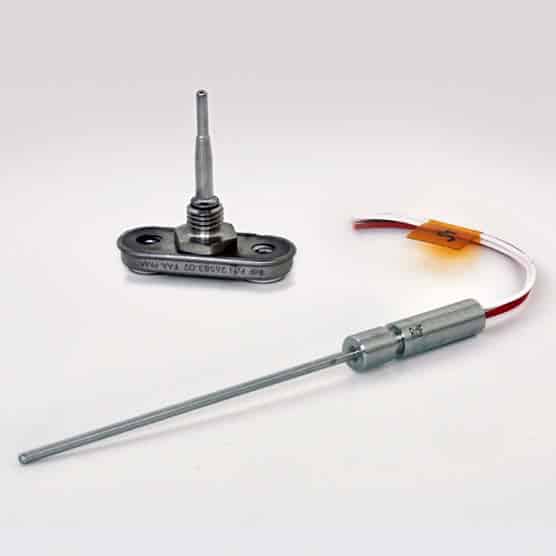
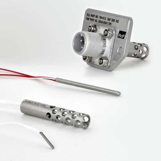
Engines

RdF supplies sensors monitoring turbine inlet and inter-stage turbine temperature on many of the world’s aircraft. Dependable operation over thousands of starts, stops and thermal cycles demands the reliability delivered by RdF’s thermocouples and RTDs. RdF also holds FAA-PMA approvals for manufacturing sensors to the Aftermarket.

Fuels & Fluids

RdF sensors monitor temperature in fuel and main oil systems, as well as hydraulic fluid systems. Their RTD’s are installed in various assemblies including level-sensing and flow measurement. For fuel temperature applications, their sensors have been designed for line-mounting and full immersion in the tank.

Air Temperature

RdF air sensors provide accurate measurements for critical applications in environmental control systems, controlled chambers, wind tunnels, cargo bays, air intakes, heat exchangers, and exhaust flues. Configurations vary depending on system requirements, from simple sheaths to perforated sheaths, with either thermistors or RTDs covering a broad temperature range.

Transparencies & Structures

RdF’s resistance temperature sensors are integrated into the de-icing systems of commercial and military aircraft. Standard and custom components are incorporated into leading edge and rotor blade assemblies as well as various composite components use throughout the aircraft. Transparent wire-wound grids or point-sensitive RTDs are laminated into windshields and canopies with high optical clarity requirements. The stability and repeatability of RdF’s sensors mean consistent and reliable readings over the aircraft’s service life.

Cryogenic Aerospace RTDs

RdF offers a broad range of Cryogenic RTD Probes for ground support and flight. We tailor designs and qualify sensors to meet varying performance requirements and environmental conditions for each program. RdF RTDs have served on every manned US Space Mission since Project Mercury.

Cryogenic RTDs for Aerospace often have application-specific demands that are met with different design options. These particulars will vary and should be discussed with RdF to identify the right sensor. Examples of such considerations are:

• Dynamic Requirements, shock vibe and flow
• NIST Traceable Cryogenic Calibration for High Accuracy Control Points

Typical Performance RangeConstruction Features
Temperature Range-320°C to 200°C Max (-434°F to 500°F)Hermetically Sealed
Standard AccuracyTyp ±1.1°C Over Temp RangeAll-Welded Metal Construction
Special Accuracy±0.14°C at Custom CalibrationThread Mount AS5202
Pressure Rating2,500psi - 5,000psi OperatingLockwire Holes
Resistance at 32°F / 0°C100Ω, 1000Ω, 2000ΩTypical Connector D38999 or Custom
Sensor StyleFeaturesNotes
A - Straight sheath probe
A Straight sheath probe
  • Response Time 3 seconds
  • 0.25" Outer Diameter
  • 6", 12" Probe Length
  • Connection: Leads or Connector

General Use Ground Support Design
Installation with Swagelok Fitting

B - Stepped sheath probe
  • Response Time 1-2 seconds
  • 0.125" to 0.188" Tip Outer Diameter
  • Configurable Length, 2" and up
  • Process Thread Mount

General Use Design
Robust constuction, well suited for high flow measurement

C - Small diameter probe
  • Response Time 1 second
  • 0.093" to 0.125" Tip Outer Diameter
  • Configurable Length, Up to 2"
  • Process Thread Mount

General Use Design

D - Flat responce probe
  • Response Time 0.5 seconds
  • Variable Tip Outer Diameter
  • Configurable Length, from 1.5"
  • Process Thread AS5202

Available with and without Tip Shield based on flow conditions
Stainless or Inconel construction typical
Connector D38999

E - Hollow Annulus Probe
  • Response Time 0.3 seconds
  • 0.33" Outer Diameter
  • Configurable Length, 3" -6"
  • Process Thread AS5202

Robust constuction, well suited for high flow measurement

Calibration Capabilities

RdF maintains a NIST-traceable calibration facility to support the high accuracy requirements of our Research, Defense, Aerospace and Nuclear customer base.
 
For many applications, RdF recommends a standard three-point calibration at Liquid Nitrogen, 0°C and 100°C to provide reliable and repeatable measurements ±1.1°C over a wide range.
For customers with super high-accuracy sensing needs, RdF Corporation offers multipoint cryogenic calibration services and individualized Resistance v Temperature profiles in the cryogenic range for each probe. Calibration points can be customized to application-specific control points.
 
Using our NIST-Calibrated Cryogenic Standards, RdF’s calibration process yields RTD Probes with accuracies ±0.14°C, high interchangeability, and extremely stable, repeatable performance.

RdF Aerospace Legacy

Founded in 1955, RdF has supported space exploration since the inception of the United States Space Program. RdF sensors have served on every manned U.S. space mission since Project Mercury.
Their qualified temperature sensors are orbiting on the ISS, satellites, and telescopes, installed in ground support facilities, and monitoring critical systems on launch and crew vehicles currently in production.
 
Today, RdF continues to work with companies worldwide to advance the exploration of Space. To discuss your project or learn more about RdF’s Cryogenic Capabilities, please speak to one of our engineers.

Current measurement in E-Mobility

Isabellenhüttes Busbar Shunts – Your solution for current sensing battery management systems & high-current application

The automotive industry is currently undergoing a transformation. Electromobility is gaining in importance in all vehicle sectors – from passenger and commercial vehicles to passenger transportation. The focus here is primarily on the complete electrification of vehicles and less on the hybrid technology that has been widespread to date. Accordingly, pure electric motors and their components must become increasingly powerful, precise, reliable and durable.

Both hybrid and electric vehicles are typically high-current applications in which an accurate battery management system (BMS) is of great importance. Three central parameters must be recorded as accurately as possible in the BMS in order to provide accurate information about the range of an e-vehicle: the cell voltage, the cell temperature and the current flow. Isabellenhütte’s busbar shunts and analog sensors are suitable for measuring high currents. This white paper covers the features, characteristics and possible applications of the different busbar shunt variants. It explains what distinguishes the components of the Isabellenhütte component as well as their specific use cases.

The Basics

Basics of busbar shunt current measurement

Current measurement across a measuring resistor works by measuring the voltage drop directly across the resistor: 
Source Voltage (U) = Resistance (R) x Current (I) + Thermoelectric Voltage (Uth) + Induced Voltage (Uind) + Voltage drop across leads (Uiext).

The analog measurement signal is amplified, then converted into a digital signal and provided to the evaluation electronics. In this case, fault voltages not caused by a current flow (e.g., due to influences of the material or the design) can falsify the measurement result – especially in the case of low-ohmic shunts where the voltage drop is very small. Also to be considered is the power dissipation, which cannot be neglected at very high currents.

Isabellenhütte’s resistance materials are physically optimized in such a way that disruptive influences are kept to a minimum from the outset. The matching design and optimized PCB layout also improve the measurement performance of the resistor. Due to the low-ohmic values of the shunts, the power loss and thus the heating in the component can also be kept low. In addition, the components maintain the specified tolerances in the complete temperature range, at full load and over the entire life cycle.

Long-term stability

Long-term stability is an important parameter with regard to the quality of a current sensor, which is evaluated as a function of the operating temperature. Isabellenhütte’s busbar shunts are characterized by very good long-term stability. The temperature-related drifts are only slight, even in continuous use. To achieve this, the resistance materials must be stable against corrosion and not undergo any metallurgically induced changes of state. During production, the resistance alloys undergo a temperature stabilization process that optimizes the long-term properties of the components. Stability values in the ppm range per year are possible with these alloys.

Image 1: The graph shows the long-term stability at 140 °C after 2,000 h.
Temperature dependence

When considering the temperature dependence of resistors, the temperature coefficient TCR plays an important role. This coefficient indicates how much the resistance value changes over a given temperature range and is measured in ppm/degree of heating (in Kelvin). The smaller this change due to heating, the better it is for the application.

There are other factors that can affect the temperature coefficient, such as the contacting capabilities. If the connection is not made properly, the temperature coefficient of the resistor may be distorted due to the influence of the measuring line or contacting.
The Isabellenhütte busbar shunts already have a very good TCR value. Optimized positio¬ning of the contacting options, as recommended by Isabellenhütte, can further improve the TCR value. This reduces the measurement error in the overall system; the user receives the best possible measurement result.

Image 2: TCR graph for Manganin®

Load capacity

The busbar shunt manufacturing process has an extremely positive influence on the load capacity of the busbar shunts. Due to their special structure, the heat generated in the resistor material is efficiently dissipated through the welded copper terminal, which has high thermal conductivity and heat capacity. Due to their high electrical conductivity, the solid copper terminals in turn ensure uniform current density and heat distribution in the resistor. This results in a low internal heat resistance.

Due to these properties, the resistors can withstand a high load at full power up to very high terminal temperatures – the derating point of the so-called power derating curve is therefore high. This manufacturing process avoids hotspots and achieves a high pulse and continuous load capacity.

The Standard Busbar Shunts

Standard busbar shunts

The standard busbar shunts are components for high current applications that do not have a contacting option of the kind integrated in the analog sensors. In this case, the voltage taps must be connected by the customer. The busbar shunts are used in 12 V, 24 V and 48 V applications as well as in high voltage applications at > 400 V. They form the basis fora current measurement in the Battery Junction Box (BJB), alternatively also called the Battery Disconnection Unit (BDU), and are produced using electron beam welding technology.

They consist of two copper strips that are electron-beam-welded together with a resistance alloy (with a high copper content) to form a composite material. Thanks to this technology, they offer a high degree of flexibility, as the composite material can be adapted to a wide range of shapes and applications in terms of stamping and bending. Isabellenhütte’s various resistor series comply with the RoHS directives and are qualified in accordance with the high requirements of the AEC-Q200 standard for the automotive sector.

Image 3: Electron beam welding process

Isabellenhütte BAS Series

The BAS is the basic version of the busbar shunts for current measurement of battery currents. Possible applications include all types of hybrid and electric vehicles such as cars, trucks, forklifts or industrial trucks. Other potential applications include current measure-ment in welding equipment or in stationary or mobile energy storage systems. The trend with regard to the use of busbar shunts is clearly moving towards ever lower resistance values. The higher currents that must now be measured in the e-mobility sector are also accompanied by higher power dissipation, so developers want to keep this to a minimum by using resistors with the lowest possible resistance values.
 
The BAS is available with resistance values of 35, 50, 100, 200 and 500 μOhm. Depending on customer requirements, there are now around 30 standard variants of the BAS: with two or four holes, with different hole diameters, without holes, in different lengths, in tinned and untinned variants. On the one hand, tin plating can protect the base material of the bus bar, copper, from corrosion. On the other hand, the tin plating achieves a very low contact resistance, which inevitably occurs between the shunt and the bus bar when they are screwed together. With tin as the surface material, this contact resistance is somewhat lower thanks to the soft nature of tin.

Isabellenhütte BAL Series

The BAL is the smallest busbar shunt in Isabellenhütte’s portfolio. It is ideal for 12 V battery management systems in all vehicles. In addition, it is potentially of interest to customers looking for a standard solution for the conceptual design of an energy storage system. Power losses of up to 12 W and a continuous current of 350 A with an R-value of 100 μOhm are no problem for the BAL. In the untinned version, the shunt offers the possibility for integration in a bus bar via laser welding, while the tinned version helps to reduce the contact resistance via a classic screw connection on a bus bar.

Isabellenhütte BAN Series

The standard busbar shunts also include the BAN. With a size of 84 x 36 x 3 mm (L x W x D) and a low resistance value of 25 μOhm, the BAN is ideal for monitoring very high currents above 1,000 A, especially for high voltage BMS applications in PHEVs and BEVs. The BAN is also available as a TCR-optimized version, making it ideal for highly integrated solutions with very high accuracy. In addition, the shunt is available with two or four mounting holes for screwing onto the bus bar.

Isabellenhütte BAX Series

The BAX is currently the most powerful busbar shunt with the largest cross-section in the standard portfolio (84 x 36 x 4 mm, L x W x D). It was developed specifically for high-voltage batteries in electric vehicles. It is designed for currents of over 1,000 A. Hybrid vehicles use smaller electric motors with 48-volt systems, while pure electric vehicles are high-voltage applications with voltages from 400 to 800 V or higher.
 
In this respect, the performance requirements for the component are also extremely demanding. It must be able to handle a continuous high current, in some applications 500 to 1,000 A – permanently.
 
Such extreme power loads require resistors with a larger construction and lower resistance values to keep power losses to an absolute minimum. In addition, the BAX must also be able to withstand fault conditions such as short circuits when 2,000 or 5,000 A occur in a few milliseconds. In these high-current applications, the long-term stability of the busbar shunt is also crucial, as this has a direct influence on the residual range indicator in the vehicle. The more accurately the current can be measured over a long period of time, even at different temperatures, the more accurate the indication of the remaining range will be. The BAX meets the high requirements for fault tolerance over the life cycle of the component. The extremely low-ohmic BAX shunt is currently available in two variants; one with a resistance value of 20 μOhm, the other with a corresponding value of 5 μOhm.

Analog Sensors

Higher integrated shunt solutions

Higher integrated shunts are solutions that not only consist of the shunts themselves, but also include voltage taps and contacts, which are provided on the shunts in various forms for the customer. Various solutions are available on the market.

Analog sensors with PCB

The analog sensor with PCB is a busbar shunt that can either be developed on a customer-specific basis or selected from Isabellenhütte’s standard product range. In addition, it contains a soldered-on printed circuit board (PCB), via which, among other things, direct tapping of the measurement signals is possible. Furthermore, depending on the configura¬tion, the temperature can be measured via NTCs (Negative Temperature Coefficient Thermistors) on the PCB and the resulting values can be used to compensate for the temperature coefficient.

Depending on the configuration, the analog sensor thus fulfills two of the main functions of a battery management system: current measurement (CSM) and temperature measure¬ment (TMP).

On the one hand, this ensures reliable transmission of measurement signals and also eliminates an additional process step. A connector is used to tap the voltage and tempera¬ture values and transmits the analog signal to the customer’s higher-level system.

The advantage for the user: The user gets a very good measurement signal because the PCB is placed exactly where the temperature coefficient is most favorable. If the user chooses his own contacting, this could be at a point where the TCR cannot be measured optimally, so that the measurement result is negatively influenced. On the other hand, with the PCB applied directly to the edge of the resistance material, the best possible pickup of the measurement signal is guaranteed.

The analog sensor with PCB also promises greater flexibility in terms of installation space: The system does not need to be designed in a special way so that the shunt and separate PCB are as close to each other as possible. It should be noted that the lead to the higher-level PCB can act like an antenna and thus interference can be received. However, this problem can be solved with a twisted or shielded lead.

Further variants – with different resistance values and shunt dimensions, and with ISO26262 qualification and more – are currently in the development phase and can be requested.

Another plus: On request, Isabellenhütte can laser the actual R-value of each manufactured component, including the temperature coefficient curve, onto the shunt in the form of a DMC code. The customer thus receives a “quasi-plug-and-play” solution and can use it immediately in the target system.

Isabellenhütte BSS current sensing shunt resistor with Molex DuraClik connector product image
Isabellenhütte BSS Series
Isabellenhütte BSN Series
Image 10: The analog sensor with PCB - a general overview

Analog sensors with press-fit pins

An alternative to connecting the shunt via a PCB with connector is to subsequently attach a PCB (developed by the customer) via a press-fit connection.

In this area, Isabellenhütte has responded to market requirements by providing another contacting option with press-fit connections, which allows the customer’s main PCB for the application to be directly contacted with the shunt via the press-fit pins. The attach¬ment of the press-fit pins offers some flexibility in terms of the position and number. In the areas of the press-fit pins, the busbar shunt must be uncoated, whereas coating is possible at the connection points to the bus bar in order to reduce the contact resistance.

The press-fit pins are conventional press-fit connections in accordance with IEC 60352-5. Isabellenhütte offers three different standard heights for these pins, although custom heights and other pin variations are also possible.

Three BAS shunts with R-values of 35, 50 and 100 μOhm and two press-fit pins each are available as standard. Customized designs can be easily implemented.

The advantages of this press-fit technology include the ability to quickly create connections without soldering. In addition, the distance of the PCB from the shunt provides protection in case of excessive temperatures at the shunt, which could possibly damage the PCB. Furthermore, at high currents, the distance between the PCB and the shunt can also reduce the influence of the magnetic fields on the semiconductors located on the PCB, which are sensitive in some areas.

Other contacting solutions

Contacting a busbar shunt with a PCB or press-fit pins covers nearly 80 – 90% of the total busbar shunt market. In addition to these two solutions, another contacting option should be briefly mentioned: a flex lead applied to the shunt, the bonding of wires to the shunt, THT (through-hole technology) construction. The remaining solutions, such as flex lead or wire bonding, also play only a minor role for cost and technology reasons. The THT design is mostly used in industry, but less so in the automotive industry.

Conclusion: High flexibility in contacting

The key point of the BAx series, apart from its suitability for high-current applications – from electric vehicles to welding equipment – is the flexibility in terms of contacting to the customer’s measuring system. Depending on installation space, size and measurement requirements, users can choose from numerous options: according to resistance values, tinned/untinned design, with integrated printed circuit board, soldered pins or from individual solutions such as flex cables or metal injection moulding.

In the consultation, it is important for Isabellenhütte to show that the good properties of the busbar shunts can only be used optimally if the customer-side connection within the application is also considered. The contacting of the current sensor is part of the best possible measurement result. A wide variety of influencing variables must be taken into account in advance. Isabellenhütte will be happy to advise you on the development of a viable measurement solution that takes all influencing factors into account.

Isabellenhütte. “Busbar Shunts for Current Measurement in E-Mobility” Published August 2023. IHH_WP_busbar_shunts_for_current_measurement_emobility_en.pdf (isabellenhuette.de)

Electromobility / Traction batteries

IVT-S Supports BMS for Lithium-Ion Traction Battery Systems

An electric drive for vehicle applications consists in principle of the following components: electrical converter, HV box / power distribution unit consisting of pre-charge circuit, fuse, protection in the negative and positive pole of the battery as well as the traction battery or mobile electric energy storage unit, including the battery management system (BMS).

High Quality of the Battery Diagnostics Parameters of the BMS due to the IVT-Series
 

The battery management system of a traction battery has two main functions. On the one hand, the active or passive balancing of the individual lithium-ion cells.

On the other hand, the calculation of the battery diagnostics parameters of the traction batteries state of charge, state of health and state of function. Determining the state of charge requires a particularly precise and high-resolution total current measurement, which is transmitted by the IVT-Series to the BMS via CAN bus.

The resolution in the mA range also allows for the detection of the standby currents, also referred to as leakage currents.

Highly Integrated Sensor with Additional Functionalities


Due to the additional voltage measurement, the IVT-Series also allows for the monitoring of the total battery voltage, the pre-charging circuit, the circuit breaker and the fuse.

The highly integrated sensors not only capture the raw data for current, voltage and temperature measurement, but also determine the power, energy and ampere-hour values on the software side as integrated values and transmit these directly to the BMS via CAN bus.

Our customers thus receive a dynamic, stable, calibrated and compact current and voltage measurement system that also offers real advantages in terms of the total system costs.

Galvanic Isolation up to 1,000 VDC Permanent


The development of higher energy densities in lithium-ion technology is leading to ever-increasing system voltages, which is why the IVT-Series provides a permanent galvanic isolation of 1,000 V DC.

Isabellenhütte. “Electromobility.” Accessed May 16, 2024. https://www.isabellenhuette.de/en/precision-measurement/applications/electromobility.

How to power on a battery operated medical or IoT device

Options and Considerations to Extend Battery Life

Battery-operated, wirelessly-connected devices are becoming increasingly pervasive in today’s society.  Driven forward by advancements in wireless and battery technologies, coupled with shrinking electronic components that consume less power, and cloud-based services ready to collect, analyze and disseminate data, these devices are commonly found in consumer, medical and wearable devices as well as in commercial, and industrial applications.

Whether the device is a wearable continuous glucose monitor (CGM), an ingestible or implantable medical device, or a smart home device, asset tracker or environmental monitor, all share the common requirement of small size, long life, reliability and ease of use. One of the major problems faced by designers of these products is powering on the device when needed.

Powering on an IoT device only when it is needed (or keeping it powered down before it is deployed) is vitally important because designers want to use the smallest, lowest cost battery possible.  For this reason, extending battery life is always a design goal; battery drain must be minimized during use as well as before it has been powered on.

One popular example is the continuous glucose monitor (CGM) prescribed to a Type 1 or Type 2 diabetic. This device adheres to a patient’s body, continuously monitoring his/her glucose level.  Resulting data is wirelessly transmitted to the patient, doctor and/or insulin pump.  CGM’s must be very small, “water proof”, easy to attach and have a reasonably long life before they run out of battery power. 

There are three basic options for powering on these devices at the point of use or deployment. For each of these options, essential variables for consideration are battery current drain, size, ingress protection and user friendliness.

The first “Power ON” option is electromechanical or the common “switch.” This option is the means for powering on most battery-operated electronic devices such as laptops and phones. Although switches come in many forms, (e.g.; push button, slider or toggle) they operate on the same principle of opening and closing a mechanical contact to allow current to flow (when closed) or completely prevent it from flowing (when open).  With regard to the first consideration of current drain, the electromechanical switch is highly efficient because it is a passive device which consumes no power.  However, in terms of size, mechanical switches are a poor option, especially given the size constraints of many wearable, ingestible and implantable medical devices and other small IoT devices. In terms of ingress protection, (or need to have a device that is impermeable to water and humidity) mechanical switches are not the best option as designing a switch that can be mechanically moved by the user into on/off positions while maintaining impermeability is challenging. Lastly, the consideration of user friendliness, or ease of use, rates poorly with mechanical switches for two reasons – first: since the user must actually take this step (and many need to be instructed to do so), the requirement for many devices is “out-of-the-box  turn-on” –  a clear conflict with manually operated switches. Secondly, a very small mechanical switch, necessitated by a very small device, could pose a problem for users’ ability to actually move the switch to the ON position, thereby reducing usability. So, in summary, mechanical switches score highly in terms of current consumption but very low relative to ingress protection, size and ease of use.

Wireless power on is the second option to analyze. Because the devices already have wireless capabilities to transmit data, designers could technically use that same wireless capability to power on a device from a mobile phone app. From an ingress protection standpoint, powering on wirelessly is rated very highly. And, from a size standpoint, powering on wirelessly also rates highly as there is nothing more to add to the device for this functionality. However, from a current drain standpoint, wireless power on scores extremely low because a wireless receiver inside the device must be powered on to receive a signal to power on. For this reason alone, wireless power on is rarely used for devices that have stringent battery life requirements.

The third option is the use of a magnetic sensor inside the device to initiate the power on function. In this case, a magnetic field is applied to the sensor to trigger the power on.  The magnetic field is typically produced by a magnet that is located within the product’s packaging or in an auxiliary component to the device (such as an applicator for a CGM). The magnetic field can also be applied by the user swiping across the device with a hand held magnet. Magnetic sensing scores very highly for ingress protection (because it is a “contact-less” method).

Magnetic sensing also scores very highly in ease of use – especially when the magnet can be embedded in the device packaging (enabling “out-of-the-box power on”) or in an auxiliary component to the device (e.g.; an applicator). Sometimes the device, itself, is designed as two components that must be connected together at the time of deployment.  In terms of current drain and size, the desirability of magnetic sensing depends entirely on the magnetic sensing technology.  Older, more traditional magnetic sensing technologies types were either small in size, but high in power consumption (Hall Effect) or large in size with zero power consumption (reed switches).  However, many new devices are designed with a newer magnetic sensing technology called Tunneling Magnetoresistive (TMR) which offers both very small size (as small as an LGA-4) and extremely low power consumption, similar to the reed switch. In effect, TMR magnetic sensors offer the “best of both worlds.”

With the current onslaught of new devices designed to make life easier, safer, contact-less and/or operable remotely, electronic designers are having to adopt new technologies to keep up with the evolving requirements of battery-operated wearables, implantables, ingestibles and other IoT devices.  In terms of best capabilities relative to small size, lower power consumption, ingress protection and ease of use, magnetic sensors – and TMR sensor technology in particular – are helping to make “impossible” designs possible.

For further information, including advice on battery types not included in this report, please contact one of our engineers today!

Caption (for above picture): The TMR Magnetic Sensor offers almost zero power consumption in an ultra-miniature package size; and its contactless “power on” capability promotes ease of use.


Related Products - TMR Magentic Sensors

ABOUT THE COMPANY

Established in 1917, Coto Technology (www.cotorelay.com) is a worldwide market leader in the design and manufacture of advanced, high-reliability switching and magnetic sensing solutions sold into the Medical, Automotive, Data Acquisition, Instrumentation, Process Control, Telecommunications, Automatic Test Equipment and Security markets.  RedRock® is a registered brand of Coto Technology’s Sensor Product line.

Stationary electric energy storage

IVT-Series as a Link between Generation and Consumption

Home/commercial/industrial storage is the answer to the feeding of decentralized generated electric energy into the power distribution network. The rising state-subsidized expansion of renewable energies is increasingly leading to unstable situations in the distribution network. The charm of the self-sufficient energy supply is what is attractive about the home storage applications up to a few kW of power. The avoidance of peak power consumption, however, is what is attractive about commercially or industrially operated large storage applications up to a few MW of power. In UPS systems, however, an environmentally independent energy generation is usually relied on, such as CHP or a diesel generator. All stationary electric energy storage units combine the need to measure current and voltage precisely.

ICD Series combats high cost pressure with home storage applications

The home storage applications in the B2C market are under extreme cost pressure. However, the demand for an accurate and particularly high-resolution current measurement of the charging and discharging currents still exists. With the ICD Series, a concept has been developed that exclusively focuses on a digital and calibrated current measurement as well as an ampere-hour metering. Due to the low system voltage, a galvanic isolation can be done away with and the ICD SERIES can meet the relatively low nominal currents under 100 A with a very compact design and resolution of 1 mA.

IVT Series Daisy-Chain Functionality for Large Commercial/Industrial Storage Units

With large electrical energy storage units, several stacks of very high power are connected depending on the application case. Each stack has its own BMS. The system voltages of these stacks are now between 800 and 1,000 V due to the lithium-ion technology. The IVT Series can be used permanently in these systems without any problems due to its galvanic isolation up to 1 kV. The precise and high-resolution measurement of the charging and discharging currents in the individual stacks as well as the option to use the voltage measurement channels to measure the stack voltage is a clear advantage of this highly integrated solution. Another advantage in the system integration of the IVT SERIES is the ability to loop the supply voltage and the CAN bus. The sensors can thus easily be connected in a type of daisy chain from stack to stack and be addressed via configured CAN IDs.

IVT Series Supports Supply Security in UPS Systems

A battery-powered uninterruptible power supply unit (UPS) has many application areas, such as server centers, hospitals, mobile communications antennas or generally for power supply in regions with a weak network infrastructure. In contrast to home/commercial/industrial storage units, the lead-acid battery is still widely used here as battery technology. If the energy feed can be influenced by means of a CHP or simple diesel generator, then the battery diagnostics of lead-acid batteries become more important. With lead-acid batteries, the IVT-Series is proven above all by the additional voltage measurement channels in addition to the precise and high-resolution current measurement. Thus, the center tap of the 48 V lead-acid system in particular is measured in addition to the total stack voltage. This facilitates the service and monitoring of the individual cell blocks during maintenance and repair. The performance always depends on the weakest cell block, especially with lead-acid applications.

Isabellenhütte. “STATIONARY ELECTRIC ENERGY STORAGE” Accessed May 16, 2024. https://www.isabellenhuette.de/en/precision-measurement/applications/stationary-electric-energy-storage.

What is hydrogen?

Hydrogen (H) is the first element on the periodic table and is the most abundant gas in the known universe. Each atom of hydrogen consists of only one proton. Despite this, there is no natural hydrogen produced on Earth as it is only found in a combined form. Water (H2O), for example, is a combination of hydrogen and oxygen. Hydrogen is also found in other forms such as hydrocarbons which are contained within fuels such as petrol, diesel, natural gasses, methanol, and propane.

Hydrogen is not actually an energy source itself, but instead an energy carrier. For this reason, hydrogen has a unique and often, at times, misunderstood role in the global energy system. One of the most significant advantages of hydrogen is that it is very efficient, approximately three times more efficient than gasoline.

One of the biggest challenges with hydrogen is obtaining it in its pure form.  Although Hydrogen is a green fuel during its usage, cracking hydrogen from its compound form requires a large amount of energy. At the current time, around 84% of the world’s energy is still derived from fossil fuels. This results in greenhouse gas emissions and air pollutants which lessen the overall environmental benefits of hydrogen power. There is also still the issue of safely storing and transporting this volatile element. There are however many schemes and government directives that are pushing for more and more renewable energy as well as ongoing projects within various companies to develop safer ways of transporting and using hydrogen. Along with a greener energy source, we are also able to produce hydrogen from biological hydrogen production, a process where carbohydrate-rich and non-toxic raw materials are broken down by anaerobic and photosynthetic microorganisms, producing hydrogen as a byproduct of this process.

Hydrogen as a form of energy carrier is not new,  powering the first internal combustion engines over 200 years ago and becoming a fundamental part of the refining industry. It has some positive benefits being light, storable, energy-dense and only having water as a by-product. Hydrogen could be the key to unlocking a carbon-neutral future. However, for this to happen it needs to be adopted into the larger industries and sectors where fossil fuels and nuclear energy are currently being used such as transport, buildings and power generation.

Can hydrogen be used as a fuel for vehicles?

A fuel cell is an electrochemical cell, that produces electricity by converting chemical energy into electrical energy. When hydrogen and oxygen are combined within a fuel cell, heat and electricity are produced, with water vapour produced as a by-product.

Fuel cells have the potential to power electric motors (used within various modes of transportation),  provide energy for systems as large as a power station or charge something as small as a mobile phone.

As with battery-electric vehicles (BEV), hydrogen fuel cell electric vehicles (FCEVs), including cars, vans, buses and lorries are powered by electricity, so produce no harmful emissions including carbon dioxide (CO2) from their tailpipe. Only water vapour is produced from hydrogen fuel cell electric vehicles. In FCEVs, energy is stored in the form of compressed hydrogen fuel, rather than in a battery. Hydrogen can be stored and transported at high energy density in liquid or gaseous form.

In hydrogen fuel cell electric vehicles (FCEVs) the fuel cell converts compressed hydrogen from their fuel tanks into electricity that powers the electric motor in the vehicle.

A fuel cell coupled with an electric motor is two to three times more efficient than an internal combustion engine running on gasoline. Therefore FCEVs have the advantage of being able to cover longer distances, and only take a few minutes to refuel at a retail site, unlike BEVs that take a long time to recharge in comparison with a much shorter range.

Pressure sensors for hydrogen applications

With the demand for hydrogen fuel cell-powered vehicles and equipment increasing, so does the need for hydrogen-compatible equipment and components. Core Sensors, a leading manufacturer of pressure and temperature transducers, produce a range of specialist pressure sensors capable of monitoring the dispensing and storage of hydrogen.

There are some known difficulties when working with hydrogen in its gas form, so selecting the correct sensor configuration is a key factor in the planning process. Two of the biggest concerns are hydrogen embrittlement and hydrogen permeation.

Hydrogen embrittlement is the degradation of a sensor diaphragm’s metal properties caused by hydrogen. To avoid this, choose the optimum sensor materials. Materials to avoid are 17-4 stainless steel and nickel-based alloys like Inconel 718.

Hydrogen permeation happens when hydrogen atoms (H2) separate into hydrogen ions (H+) under specific conditions like high pressure and temperature. These hydrogen ions can pass through the sensor diaphragm’s molecular structure.

To overcome these complications, Core Sensors have designed a range of pressure sensors, transducers and transmitters, providing a high-quality and long-life solution for your hydrogen application.

Design & Materials selection

Fluid filled sensor diaphragms are highly susceptible to hydrogen permeation and should be avoided. Hydrogen ions that pass through the thin diaphragm will form hydrogen bubbles in the fill fluid causing zero and span shifts. Over time these bubbles can expand and cause the diaphragm to bulge and eventually fail, resulting in the fill fluid leaking and contaminating the process.

To avoid having fluid filled cavities, sealing materials such as O-rings or welded joints, Core Sensors can manufacture their sensors using a single piece of 316L stainless steel. This solid piece of stainless steel then contains the hydrogen within the pressure port, reducing the possibility of the media permeating the thin diaphragms that are common in oil filled sensor designs.

High-pressure hydrogen measurement

Hydrogen is compressed to a high pressure, typically 350 Bar (~5,000 PSI) and 700 Bar (~10,000 PSI), to help increase the amount of hydrogen that can be stored on site. Highly reliable pressure sensors are required to safely monitor these tanks and other high pressure hydrogen applications. Core Sensors offer an F250C female autoclave process connection option for pressures >10,000 PSI. This process connection features all 304 and 316L stainless steel wetted parts to ensure protection from embrittlement and permeation, resulting in a long term monitoring solution.

Applications
  • Storage
  • Fuel Lines
  • Dispensers
CS50 with an F250C Female Autoclave process connection and Mini-Fast electrical connection
CS50 with an F250C Female Autoclave process connection and 1/2″ MNPT conduit w/ cable
Benefits
  • High Strength
  • 316L Stainless Steel
    UNS S31603
  • All welded metal construction
    No internal elastomer seals
  • Area Classification
    CSA Class I, Division 2 Non-Incendive Groups A, B, C, D T4
  • Marine ABS Approvals
  • CE
F250C Female Autoclave process connection in all 304 & 316L SS
Variety of configurations available (DIN 43650, Form A, Turck® Mini-Fast®, 1/2” MNPT conduit w/strain relief

Industrial applications

For industrial applications where hazardous certification approvals are not required, the CS10 Industrial Pressure Transducer can be packaged to meet the demands of hydrogen environments. Pressure ranges are available from 50 PSI up to 20,000 PSI in solid 316L SS. Customers have the choice of various output signals including 4-20mA loop powered for long-distance transmissions and voltage outputs for low power and low current consumption applications. A variety of electrical connections are available from standard DIN connections to M12x1 and integral cable for a higher IP67 rating. Custom configurations are available for OEM projects.

Hazardous – Non-incendive

Some applications require non-incendive approved equipment, the CS50 Non-Incendive Pressure Transducer is an ideal solution to this and can be configured with 316L stainless steel material and various other options. The CS50 is approved for the following standards:

  • CSA Class I, Division 2, Groups A, B, C, D T4
  • ANSI/UL 122701 Single Seal
  • ABS (American Bureau of Shipping)
  • CE

Common model number configurations

To best suit your application and installation requirements, Core Sensors are able to customise the configuration of the below parts that are typically used in hydrogen fuel cell applications.

Model NumberDescriptionTypical Use
CS10-GA00020BG2C000-00
View CS10 specifications
0-20 Bar, 3/8-24 UNF-2A Male process connection, 0.5-4.5V ratiometric output signal (5VDC regulated power supply), Packard Metripack 150, 316L SS wetted material, GaugePost regulator pressure into PEM (Proton Exchange Membrane)
CS10-4A00020BG2C000-00
View CS10 specifications
0-20 Bar, 7/16-20 UNF Male process connection, 0.5-4.5V ratiometric output signal (5VDC regulated power supply), Packard Metripack 150, 316L SS wetted material, Gauge Post regulator pressure into PEM (Proton Exchange Membrane)
CS10-GA00448BS2C000-00
View CS10 specifications
0-448 Bar, 3/8-24 UNF-2A Male process connection, 0.5-4.5V ratiometric output signal (5VDC regulated power supply), Packard Metripack 150, 316L SS wetted material, Sealed GaugeHigh pressure Hydrogen storage
CS10-4A00448BS2C000-00
View CS10 specifications
0-448 Bar, 7/16-20 UNF Male process connection, 0.5-4.5V ratiometric output signal (5VDC regulated power supply), Packard Metripack 150, 316L SS wetted material, Sealed Gauge High pressure Hydrogen storage

References

Hydrogen. (n.d.). Shell. https://www.shell.com/energy-and-innovation/new-energies/hydrogen.html

Hydrogen. (2022). Student Energy. https://studentenergy.org/source/hydrogen/

Hydrogen Pressure Sensors – Industrial & Hazardous. (n.d.). Core Sensors. https://core-sensors.com/hydrogen-pressure-sensors/

Disclaimer: Rhopoint Components Ltd provides the content on these FAQ pages for general information purposes only. All information on these pages is provided in good faith, however, Rhopoint Components Ltd makes no representation or warranty of any kind, express or implied, regarding the accuracy, adequacy, validity, reliability, availability, or completeness of any information on these pages. Users are advised that their reliance on any information provided by these FAQ pages is solely at their own risk. Under no circumstances shall Rhopoint Components Ltd be liable for any loss or damage incurred as a result of the use of the site or reliance on any information provided on the site. This includes, but is not limited to, direct, indirect, incidental, punitive, and consequential damages. The FAQ pages may contain links to external websites that are not provided or maintained by, or in any way affiliated with, Rhopoint Components Ltd. Please note that Rhopoint Components Ltd does not guarantee the accuracy, relevance, timeliness, or completeness of any information on these external websites. Rhopoint Components Ltd reserves the right to make additions, deletions, or modification to the contents on the FAQ pages at any time without prior notice.